800 Series Standard Options:
Optional Main Beam Lengths (BXXX):
Main Beams may be ordered in any length between Trunnion Interface Mounts within the limits shown below. “XXX” = length in inches between trunnion interface mounts (1″ increments).
| MODEL | MIN | MAX |
| 848 | 51″ | 371″ |
| 860 | 51″ | 371″ |
| 872 | 60″ | 380″ |
Lengths longer than MAX shown above require a special beam.
While the two End Frames can be adjusted toward each other to accommodate smaller length parts, excessively long beams with a small part will leave the Main Beams extending from each End Frame enough to be inconvenient. It therefore is desirable to order the main beam close to the size of the actual part-to-be-handled.
Lengths shorter than the MIN shown above can be dangerous due to tip over. Lengths longer than MAX shown above require a special beam.
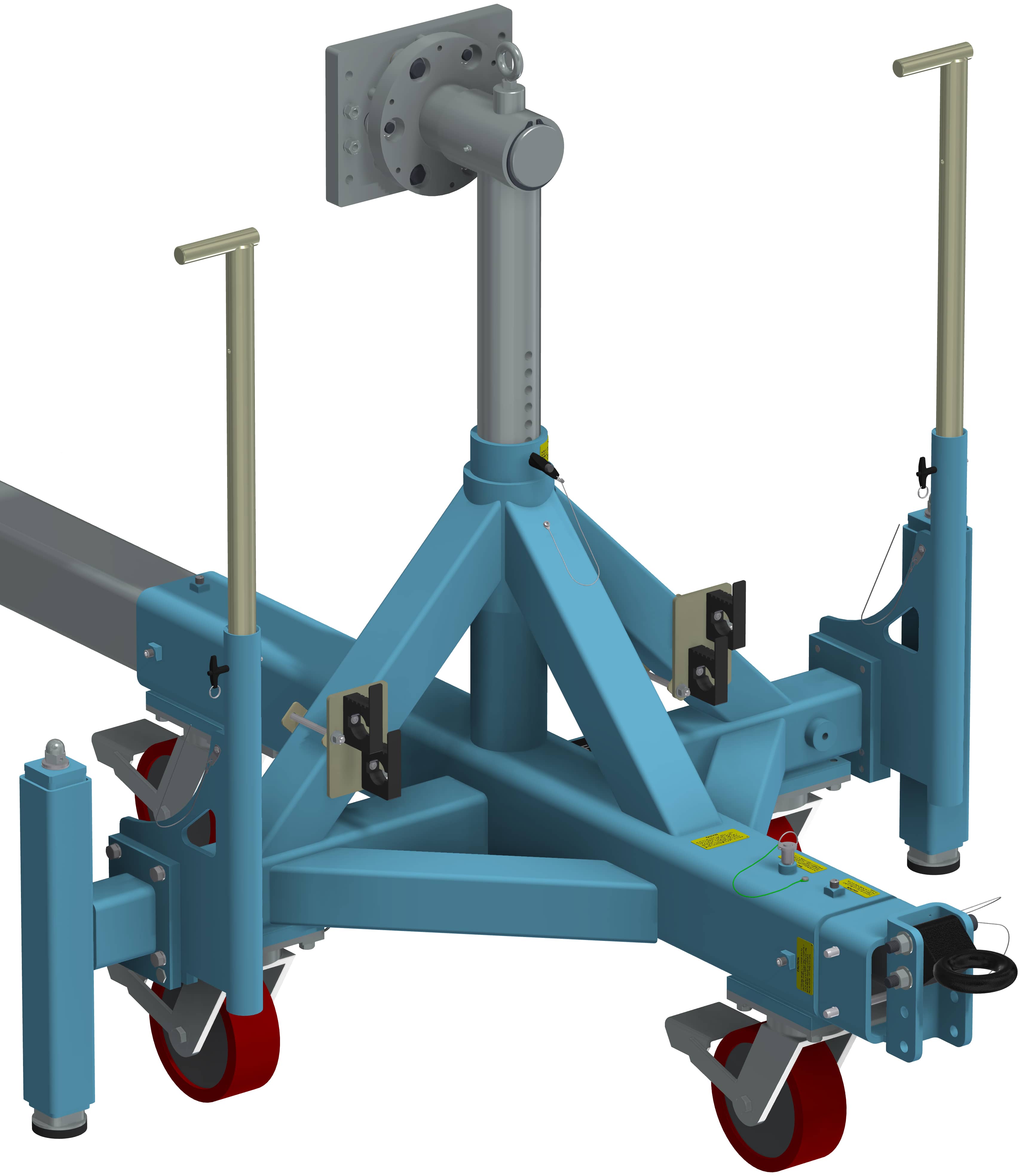
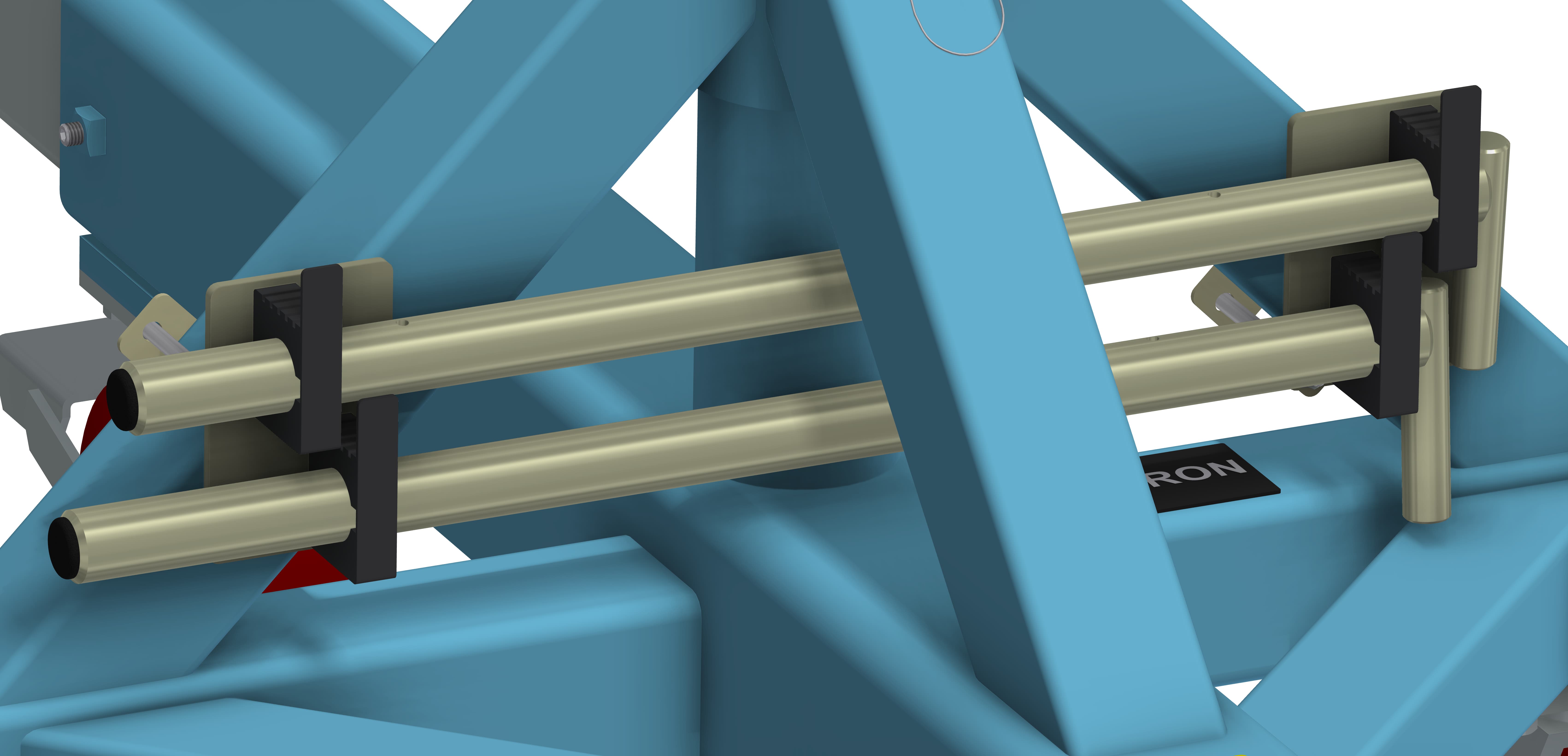
Standard Combination Mounting Plate / Angle Clamp (P12 / A30):
1. Angle Interface (A30) – The Angle Interface offers the most adaptability for customers. Either of the perpendicular surfaces of the angle may be bolted or clamped to. The standard length is 30 inches with no bolt holes. The standard finish is clear zinc plate. The A30 Angle is bolted to the P12 Mounting Plate and may be removed if the customer desires to mount directly to the P12.
2. Mounting Plate Interface (P12) – The Part-to-be-handled can be easily bolted to this flange type interface. The standard size is 8″ x 12″ with an eight-hole bolt pattern spaced at 10.5″ x 6″ centered on the plate. The eight holes will accept up to ½” diameter bolts. The standard finish is clear zinc plate.
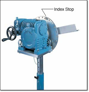
Optional Index Plate (INDSXX):
Optional Leveling Jacks (J0, J5):
Optional Fixture Finishes (N), (C):
1. Electroless nickel plating (N): This option replaces all zinc-plated parts with either electroless nickel-plated parts or stainless steel parts.
2. Clean Room option (C):
This option is identical to the (N) option but with the addition of electroless nickel-plating on the interior of the end frame slide tubes and vertical support tubes. The exterior of the gearbox as well as the exterior of the end frames are painted with high gloss urethane or epoxy paint in place of the standard textured enamel paint.
Optional Ground Lug and Drag Chain (E):
For use in electrostatically protected areas (EPA’s). Proper electrostatic discharge (ESD) grounding of the fixture must be a part of the overall EPA design. (See technical section discussion on ESD)
Optional Lubricants:
Krytox GPL 207 (L1) – The trunnions and caster swivel bearings are lubricated with Krytox GPL 207. Note that this lubricant comes standard on “C” (Clean Room) finish and does not need to be specified.
Braycote 601EF (L2) – The trunnions and caster swivel bearings are lubricated with Braycote 601EF.
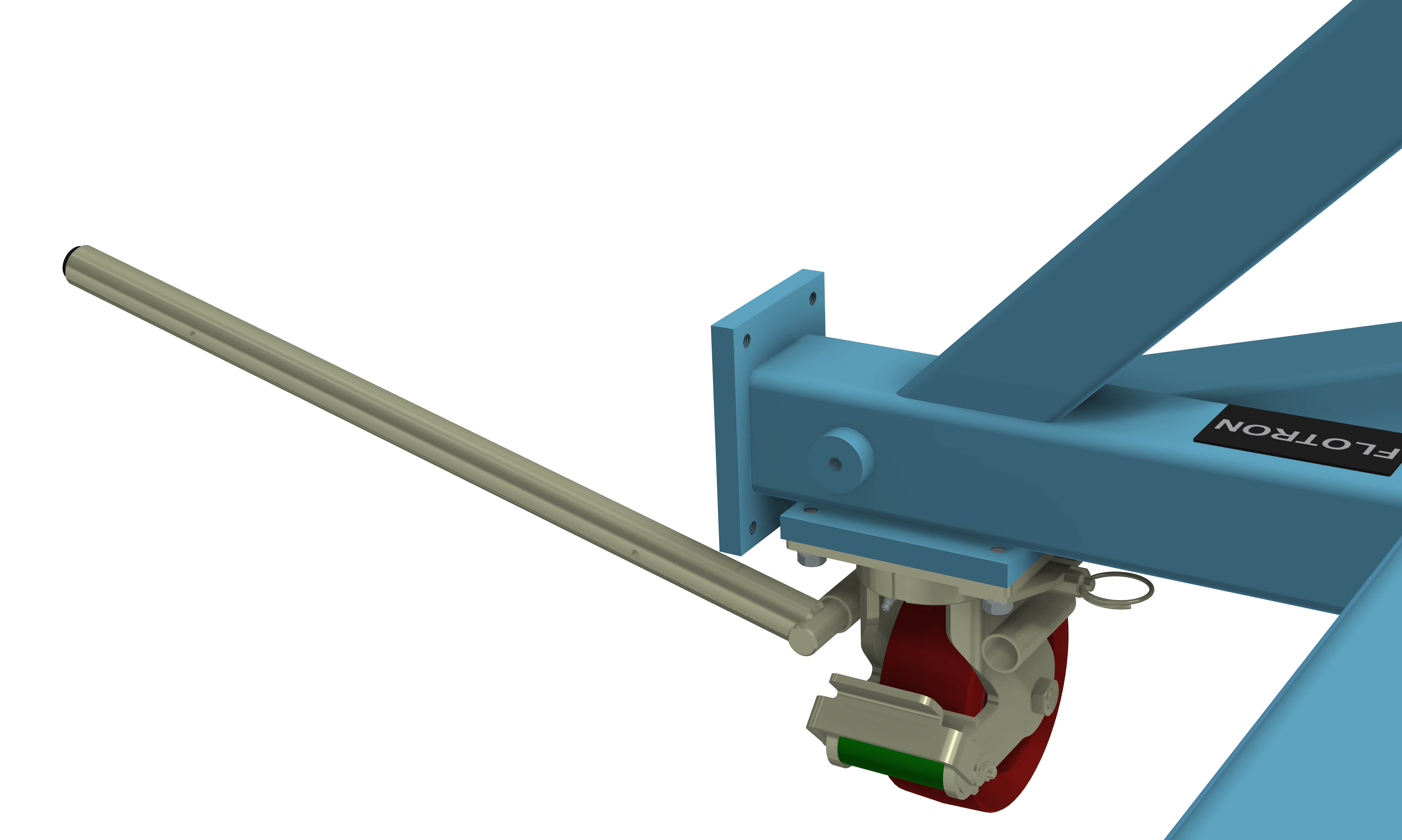
Push Bar (P1):
Push bar receptacles are mounted to the leveling jack mounting plates. A vertical bar is inserted into each receptacle to aid in pushing and steering the fixture during short intra-facility moves. The combination of having swivel locks engaged on the rear casters and bars for pushing and steering can make a huge difference to ease transportation. When push bars are not in use, they can be lowered 18” so that they are not in the way of assembly or test operations. For transportation over longer distances, it is highly recommended that the towing interface option (T1) is also added. The frame mounted push bars can be retrofitted on existing Flotron Rotation Fixtures.
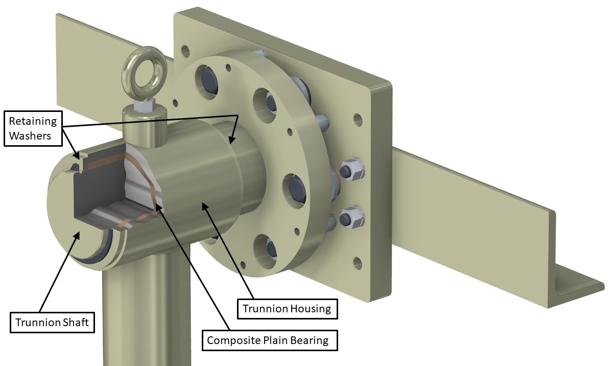
Sleeved Trunnion Bearings (B1):
PTFE composite plain bearings are placed between the trunnion shafts and the bearing housings on the non-gearbox side of the fixture. The bearings are self-lubricating and do not require any maintenance, prevent wear of the trunnions, and lower rotational friction. This option is recommended when rotational duty cycles are high (frequent rotation), when there is a long interface distance (over 100”), or when the payload is relatively flexible and sags in the middle.
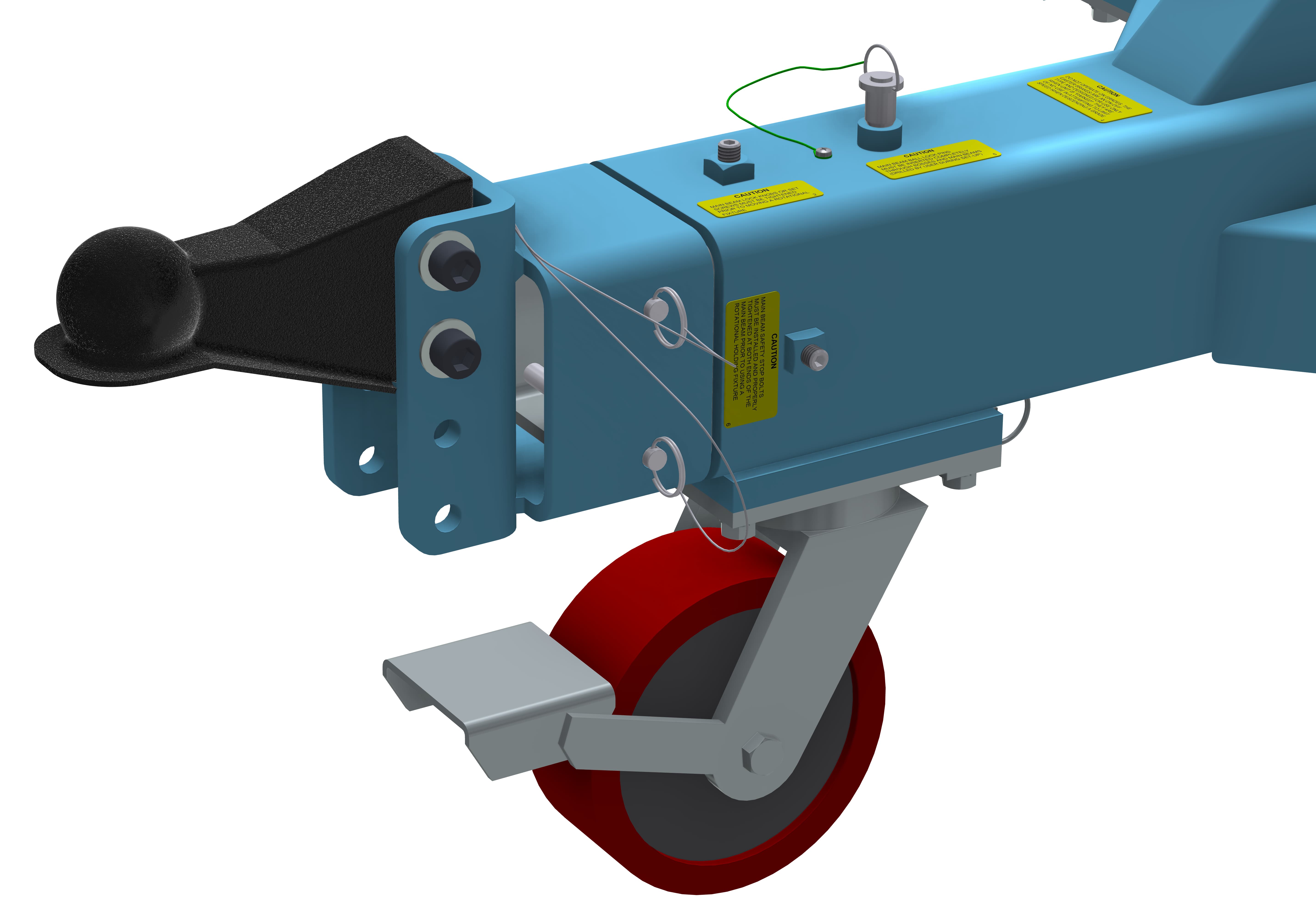
Towing Interface:
A removable towing insert is mounted to the main beam via two ball lock pins. Attached to the towing insert is either a lunette ring (T1) or ball coupler (T2) depending on which option is chosen. The Tow ring’s height can be adjusted in 2-inch increments from 12.75” – 16.75” (as measured from floor to interface centerline) by changing its position on the C-channel and lowered all the way down to 11.75” if the tow insert is flipped upside down. The towing interface option can be retrofitted on existing Flotron Rotation Fixtures.
A. Lunette Ring (T1) – The lunette ring has a standard eye that is 4.5” OD and a 2.5” ID and is 1” thick.
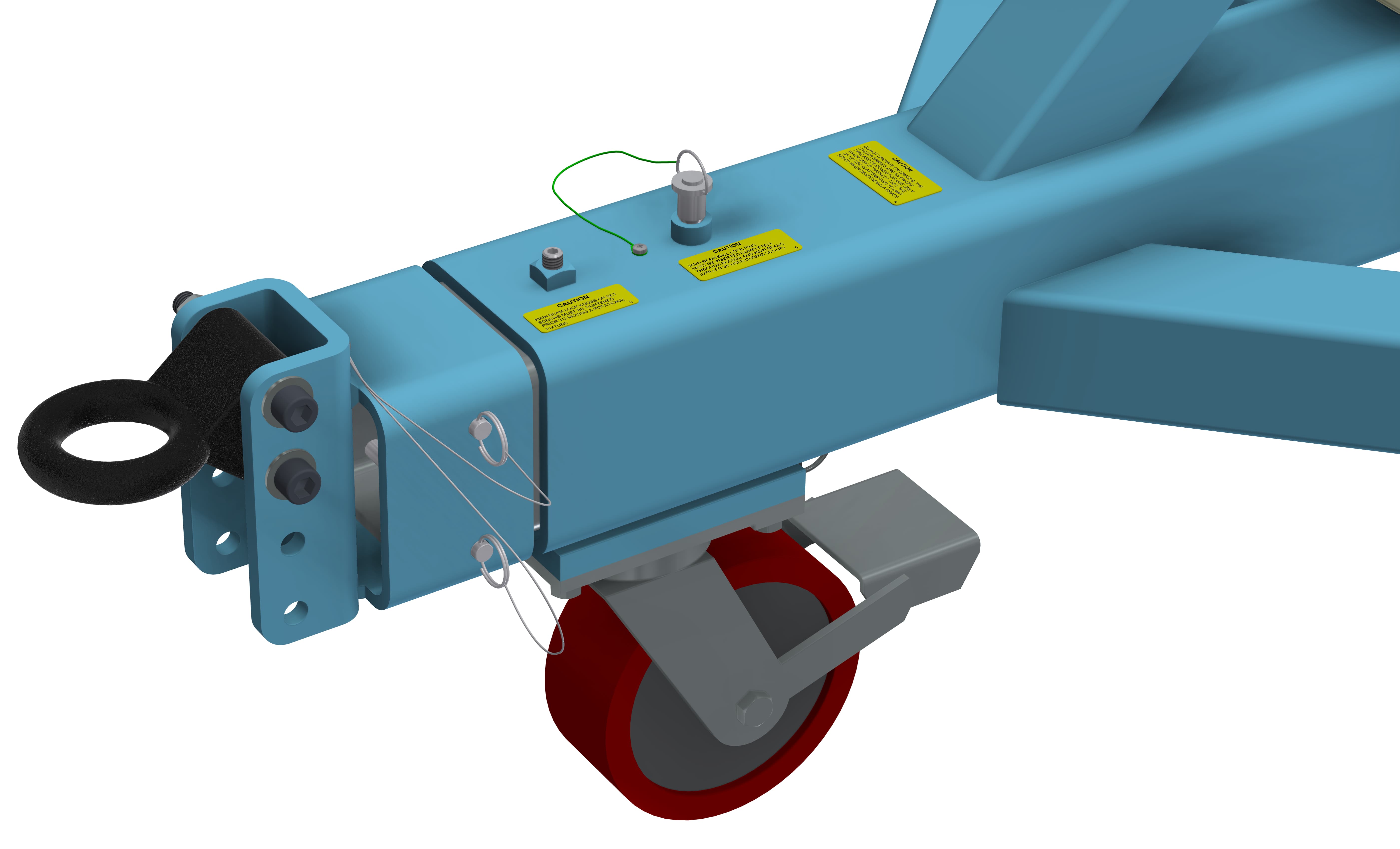
B. Ball Coupler (T2) – The ball coupler accepts a Ø2” ball.
Optional Casters:
- (Blank) – Standard Ø8” X 3” wide urethane casters with brakes & swivel locks (no steering bars)
- (C1) – Ø8” X 3” wide urethane casters with steering bar receptacles, brakes and swivel locks. The kit comes with four steering bars and steering bar stowage features mounted to the end frames. It also comes with four push bar receptacles on the leveling jack mounting plates and the steering bars can be used as push bars.
Standard Proof Load Test (PLT):
Proof Load Test Procedure:
Dead weight load (no rotation), visual inspection
- Static proof load test.
- Vertical load only.
- 200% vertical load, 100% torque.
- Hold load for 5 minutes minimum.
- Customer may witness test.
- Paint and plating covers all welds.
- Visually inspect for cracks, deformation, etc.
A deliverable proof load test report will be provided. The report will include a summary of the test procedure, actual measured weight of load applied, visual inspection results, and images of the test being performed.
Special Options:
If a standard Holding Fixture does not meet your requirements, contact Flotron about custom modifications. Often minor modifications to a standard unit are all you will need and can be done cost efficiently.See here for past examples of our Modified Standards and Custom Solutions.
For 800 Series – Creating a Model Number, click here.*