Stair-Stepping of Holding Fixture Gearboxes
-
Overview of Stair Stepping
“Stair stepping” is a jerky motion which can occur when self-locking gears are used in the “back-driving” mode. One source credits the British with having named this phenomenon “stair stepping” because the action is suggestive of the bumpy decent down a stairway.
On a Flotron holding fixture, a load with its CG located eccentric to the rotational centerline will impart a torque into the gearbox, which will tend to “back-drive” the gearbox from the 12 o’clock position toward the 6 o’clock position. The gearbox is very easy to crank during back-driving because the load CG is trying to force the gearbox to rotate in the same direction the operator is cranking and the only thing stopping the gearbox from rotation on its own is the self-locking characteristic of the gearbox. During the other ½ revolution, the operator will be raising the load CG from 6 o’clock position back to the 12 o’clock position and the gearbox becomes more difficult to crank.
It is during the “back-driving” ½ revolution that “stair stepping” can arise and cause the otherwise smooth rotation to become erratic and jerky. Some of the major causes of “stair stepping” include:
- High Inertia Loads that cause the effective inertia of the self-locking output gear to be higher than the effective inertia of the worm.
- High Torque Loads that cause a loss of the lubricating oil film on the worm when it is stationary or when it is rotating at low speeds.
- Rotational Flexibility as well as rotational clearances in the drive train and mounts, which will magnify “stair stepping”.
- Abrupt Acceleration and Deceleration that can accentuate or start “stair stepping” in borderline cases.
-
Choosing Stair Stepping Resistant Holding Fixtures
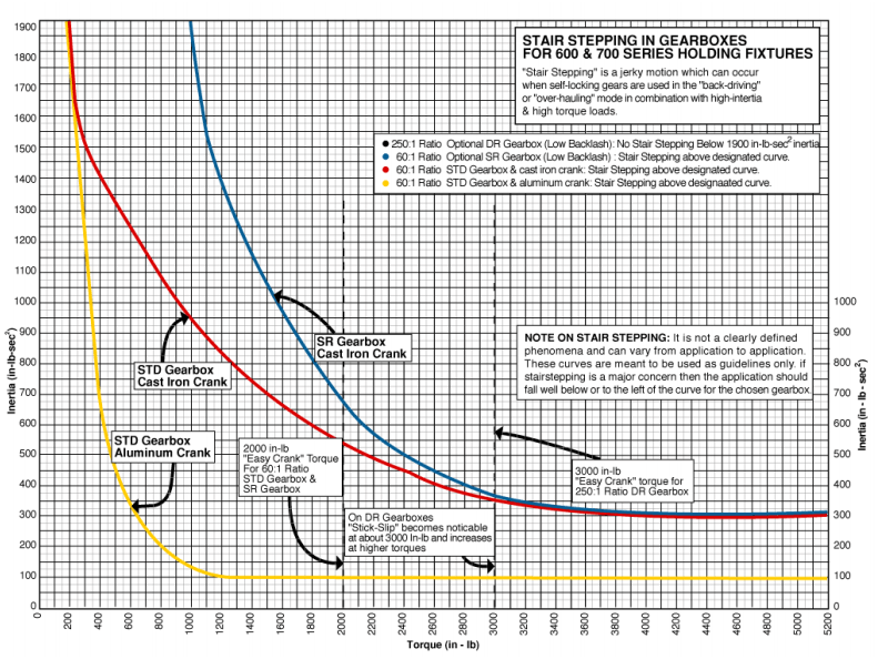
The Flotron 200, 400 and 500 series holding fixtures are typically used for positioning small parts where if “stair stepping” occurs it is not a major problem. If “stair stepping” is a concern in these units, contact Flotron with your specific application or use one of the larger Flotron 600 series holding fixtures with the appropriate Gearbox. Both the Flotron 600 and 700 series holding fixtures are offered with several gearbox options. When choosing the gearbox for your application, make certain that the combination of rotational inertia and torques fall well below the appropriate “stair stepping” curve (See graph of Stair Stepping in Gearboxes for 600 and 700 Series Holding Fixtures at the end of this section). If “stair stepping” is a major concern, use the DR gearbox (See the Creating a Model Number page in both the 600 and 700 series section). The DR gearbox has been designed to minimize “stair stepping” at all reasonable inertias.
The 800 series and larger holding fixtures are all equipped with gearboxes designed to minimize the chance of “stair stepping”.
-
Stair-Stepping Calculations
Because the 600 and 700 series Holding Fixtures offer Gearboxes with different resistances to “stair stepping”, you must approximate the maximum inertia and torque of your rotating load in order to ascertain which of the gearboxes is most suitable for your load. Use the tables to approximate the rotational inertia of your load. Use the appropriate table for square, rectangular or round shaped loads and use a size from the table that is as large or larger than the actual load. If your load is not centered on the rotational axis, use the translation formula. If your load can be approximated with several shapes, see the example calculations using the translation formula. Once the calculations for inertia and torque are complete, use the graph at the end of this section to determine which gearbox to use. Although there is a substantial cost differential between gearbox types, if the calculations fall near a curve, it is always best to use the more “stair step” resistant gearbox on borderline cases.
-
Rotational Inertia for Rectangular Shapes (in-lb-sec²)
NOTE: Many people as well as many CAD systems calculate rotational inertia without using “g” (acceleration of gravity = 386 in/sec2) and get units of lb-in2. To convert to in-lb-sec2 (units used in this section) simply divide by 386 in/sec2.
I = w (a² + b²)(in-lb-sec²)
12gmw = weight (lbs)a = side length (12in)b = side length (in)
g = acceleration of gravity (386 in/sec²)
Weight (lbs) → 100 200 400 600 800 1,000 1,200 Size b (in) ↓ 12 6 12 25 37 50 62 75 24 16 31 62 93 124 155 187 36 31 62 124 187 249 311 373 48 53 106 211 317 423 529 634 60 81 162 323 485 647 808 970 72 115 230 460 690 920 1,150 1,380 84 155 311 622 933 1,244 1,554 1,865 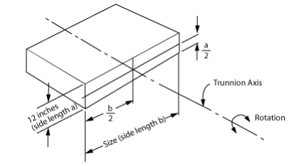
-
Rotational Inertia for Square Shapes (in-lbs-sec²)
NOTE: Many people as well as many CAD systems calculate rotational inertia without using “g” (acceleration of gravity = 386 in/sec2) and get units of lb-in2. To convert to in-lb-sec2 (units used in this section) simply divide by 386 in/sec2.
I = wa² (in-lbs-sec²)
6gw =weight (lbs)a = side length (in)g = acceleration of gravity (386 in/sec²)
Weight (lbs) → 100 200 400 600 800 1,000 1,200 Size a (in) ↓ 12 6 12 25 37 50 62 75 24 25 50 100 149 199 249 298 36 56 112 224 336 448 560 672 48 100 199 398 599 796 995 1,194 60 155 311 622 933 1,244 1,554 1,865 72 224 448 895 1,343 1,791 2,238 2,686 84 305 609 1,219 1,828 2,437 3,047 3,656 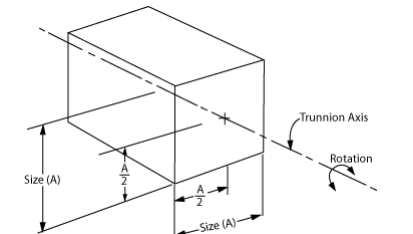
-
Rotational Inertia for Round Shapes (in-lb-sec²)
NOTE: Many people as well as many CAD systems calculate rotational inertia without using “g” (acceleration of gravity = 386 in/sec2) and get units of lb-in2. To convert to in-lb-sec2 (units used in this section) simply divide by 386 in/sec2.
I = wd² (in-lb-sec²)
8gw = weight (lbs)d = Diameter (in)g = Acceleration of gravity (386 in/sec²)
Weight (lbs) → 100 200 400 600 800 1,000 1,200 Size d (in) ↓ 12 5 9 19 28 37 47 56 24 19 37 75 112 149 187 224 36 42 84 168 252 336 420 504 48 75 149 298 448 597 746 895 60 117 233 466 700 933 1,166 1,399 72 168 366 672 1,007 1,343 1,679 2,015 84 229 457 914 1,371 1,828 2,285 2,742 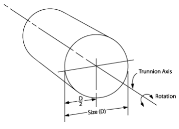
-
Translation Formula
When the shape of your load is not symmetrically located about the rotation axis, use the translation formula.
I = I0 + wh²
gI = Translated inertia (in-lb-sec²)I0 = Inertia of shape before translationw = weight (lbs) of shape
g = 386 in/sec² (Constant= acceleration of gravity)
h = Translation Distance (inches)
- Use the appropriate table to approximate the inertia of your load as if it was located symmetrically about the rotation axis. Use a shape at least as large as your actual shape.
- Estimate the distance from the center of the shape to the rotation axis.
- Use the above data to calculate the translated inertia.
-
Translation Formula Example
- Assume
weight1 = 300 lbsweight2 = 250 lbs
Total weight = 550 lbs
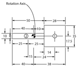
- From tables, approximate inertia1 (I1) using the shape, which is aslarge as or the next size larger than your actual shape. Therefore
use a 36” square @ 400 lbs.
I1 = 224 in-lb-sec²
- From tables, approximate inertia2 (I2) using the shape, which is aslarge as or the next size larger then you actual shape. Therefore
use a 12” x 60” shape @ 400 lbs
I₂ = 323 in-lb-sec²
- Calculate translated inertia of 1.Center of shape1 is translated 24”.
I1trans = I1 + wh²
g= 224 + (300)(24²)
386= 672 in-lb-sec²
- Calculate translated inertia of 2.Center of shape2 is translated 15”.
I2trans = I2 + wh²
g= 323 + (250)(15²)
386= 468 in-lb-sec²
- Total inertia = 672 + 468 = 1,140 in-lb-sec²
- Torque CalculationIn this example, the maximum torque reacted by the gearbox would occur when the load was rotated down to the horizontal as shown here.
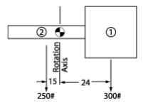
Weight1 Causes a CW Torque of (300)(24) = 7,200 in-lb
Weight2 Causes a CCW torque of (250)(15) = 3,750 in-lb
Net torque is: 7,200 – 3,750 = 3,450 in-lb
Results of these example calculations are:
Total load weight: 550 lbs
Total load inertia: ~1,140 in-lb-sec²
Total load max torque: 3,450 in-lb
- Assume
- Conclusion from Translation Formula example
Looking at the following graphs for the 600 and 700 series holding fixtures, when using either the standard gearbox or the optional SR gearbox, the load is well into the stair stepping region. Also, at 3,450 in-lb, the load is well above the 2,000 in-lb easy crank torque (12lbs on handle). However, the load is within the 5,400 in-lb torque and 960 lb load capacity of an XD759. If cranking difficulty and stair stepping is not an issue, then either the STD or SR single reduction gearbox is ok. If stair stepping or easy crank torque is a concern, then use the DR gearbox with its stair step resistant design and 3,500 in-lb easy crank torque. If easy crank torque is still a concern, then use the 800 series fixture with its stair step resistant design gearbox and 5,100 in-lb easy crank torque.