600 Series Standard Options:
Optional Main Beam Lengths (B-XXX):
Main Beams may be ordered in any length between Trunnion Interface Mounts within the limits shown below. “XXX” = length in inches between trunnion interface mounts (1″ increments).
| MODEL | MIN | MAX |
| 641 | 30″ | 120″ |
| 652 | 41″ | 120″ |
| 664 | 52″ | 151″ |
Lengths shorter than the MIN shown above can be dangerous due to tip over. Lengths longer than MAX shown above require a special beam.
While the two End Frames can be adjusted toward each other to accommodate smaller length parts, excessively long beams with a small part will leave the Main Beams extending from each End Frame enough to be inconvenient. It therefore is desirable to order the Main Beam close to the size of the actual part-to-be-handled.
Optional Trunnion Interface/Mount/Clamps:

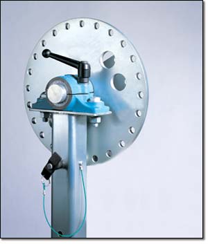
Optional Combination Mounting Plate / Angle Clamp (P12 / A30):
2. Mounting Plate Interface (P12) – The Part-to-be-handled can be easily bolted to this flange type interface. The standard size is 8″ x 12″ with an eight-hole bolt pattern spaced at 10.5″ x 6″ centered on the plate. The eight holes will accept up to ½” diameter bolts. The standard finish is clear zinc plate.
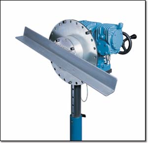
Optional Index Plate (IND15):
Indexed @ 15° increments to prevent trunnion rotation with a lock pin. The Index Plate can be supplied with the P8 Mounting Plate Interface (not on SR or DR) (shown below), the A30 Angle Interface, or the P12 / A30 Combination Mounting Plate / Angle Clamp (for SR or DR only).
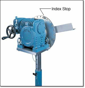
Optional Index Plate with Index Stops (INDS15):
Identical to the IND15 option shown above but with the addition of two Index Stops. The Stops can be bolted into any of the Index holes in the Index Plate to prevent rotation beyond a desired point. This can be a desirable option if your part-to-be-handled has a protrudance that could hit the main beam or floor or other obstacle when rotated beyond a certain orientation.
Optional Split Pillow Block Trunnion Bearings (SPB):
For use with lightweight balanced loads such as solar panels or wire harness boards. The Split Bearings are supplied less Gearbox and are mounted on both Risers. With each Split Bearing is a Stub Shaft that includes an IND15 Index Plate and your choice of either the P8 or A30 Interface/Mount/Clamp. Usually, the Interfaces are attached to a “customer supplied” handling frame. By removing the top half of the Split Bearings, the entire “customer supplied” handling frame and part can be removed from the fixture using an overhead lifting device. An additional feature is the Brake Handle that when tightened can clamp the Split Bearing against the Stub Shaft to create a braking resistance to rotation. Of course, to prevent rotation, the Index Pins must be inserted into the two Index Plates.
Optional Casters:
- (Blank) Standard swivel casters with Tech Lock brakes and Ø5″ X 2″ wide polyurethane wheels.
- (C1) Heavy duty Impak swivel casters with swivel locks, tread lock brakes and Ø5″ X 2″ wide polyurethane wheels.
- (C2) Swivel casters with conductive wheels, tech-lock brakes and Ø5″ X 2″ wide wheels. (not shown)
- (C3) Heavy duty Impak swivel casters with swivel locks, tread lock brakes and Ø5″ X 2″ wide elastomer wheels to improve rollability. (not shown)
- (C4) Ø5″ X 2″ wide spring-loaded casters with urethane wheels that isolates shock and vibration. Includes swivel locks and brakes. (not shown)
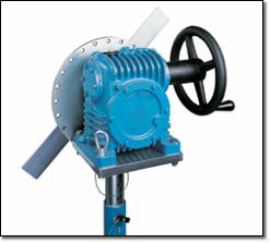
Optional Heavy Duty Gearbox:
NOTE: Addition of the optional SR or DR gearbox to the HD652 or HD641 decreases the vertical riser adjustment by 2″.
2. Optional 250:1 ratio Double Reduction Gearbox (DR): This gearbox offers heavier duty construction than the standard gearbox, plus low backlash, 3000 in-lbs easy crank torque (versus the standard 2000 in-lbs easy crank torque), and is immune to stairstepping at nearly all reasonable inertias and torques.
NOTE: Addition of the optional SR or DR gearbox to the HD652 or HD641 decreases the vertical riser adjustment by 2″.

Optional Fixture Finishes (N), (C):
1. Electroless nickel plating (N): This option replaces all zinc-plated parts with either electroless nickel-plated parts or stainless steel parts.
2. Clean Room option (C): This option is identical to the (N) option but with the addition of electroless nickel-plating on the interior of the end frame slide tubes and vertical support tubes. The exterior of the gearbox as well as the exterior of the end frames are painted with high gloss urethane or epoxy paint in place of the standard textured enamel paint.
Optional Ground Lug and Drag Chain (E):
For use in electrostatically protected areas (EPA’s). Proper electrostatic discharge (ESD) grounding of the fixture must be part of the overall EPA design. (See Technical section descussion on ESD.
Optional Lubricants:
Krytox GPL 207 (L1) – The trunnions and caster swivel bearings are lubricated with Krytox GPL 207. Note that this lubricant comes standard on “C” (Clean Room) finish and does not need to be specified.
Braycote 601EF (L2) – The trunnions and caster swivel bearings are lubricated with Braycote 601EF.
Gearbox Mounted Push Bar (P1):
The push bar is mounted underneath the gearbox and improves ergonomics of intra-facility transport of the Flotron. The combination of having swivel locks engaged on the rear casters and a handle for leverage can make a huge difference to ease transportation. The gearbox mounted push bar can be retrofitted on existing Flotron Rotation Fixtures.

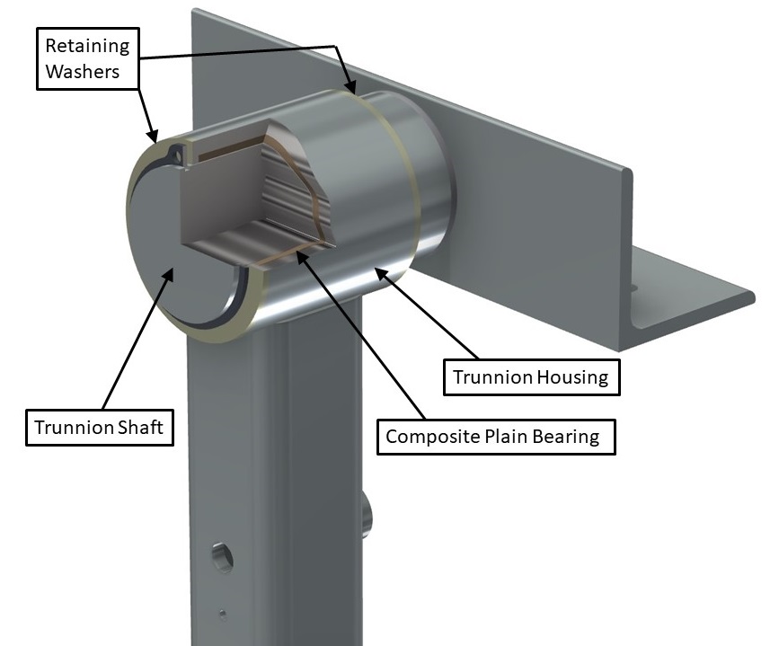
Sleeved Trunnion Bearings (B1):
A PTFE composite plain bearing is placed between the trunnion shaft and bearing housing on both vertical risers. This bearing is self-lubricating and therefore does not require any maintenance, prevents wear of the trunnions, and lowers rotational friction. This option is recommended when rotational duty cycles are high (frequent rotation), when there is a long interface distance (over 100”), or when the payload is relatively flexible and sags in the middle.
Towing Interface:
A removable towing insert is mounted to the main beam via two ball lock pins. Attached to the towing insert is either a lunette ring (T1) or ball coupler (T2) depending on which option is chosen. The tow ring/coupler height can be adjusted in 2-inch increments from 5.5” – 12” (as measured from floor to the interface centerline) by changing its position on the C-channel. The towing interface option can be retrofitted on existing Flotron Rotation Fixtures.
A. Lunette Ring (T1) – The lunette ring has a standard eye that is 4.5” OD and a 2.5” ID and is 1” thick.
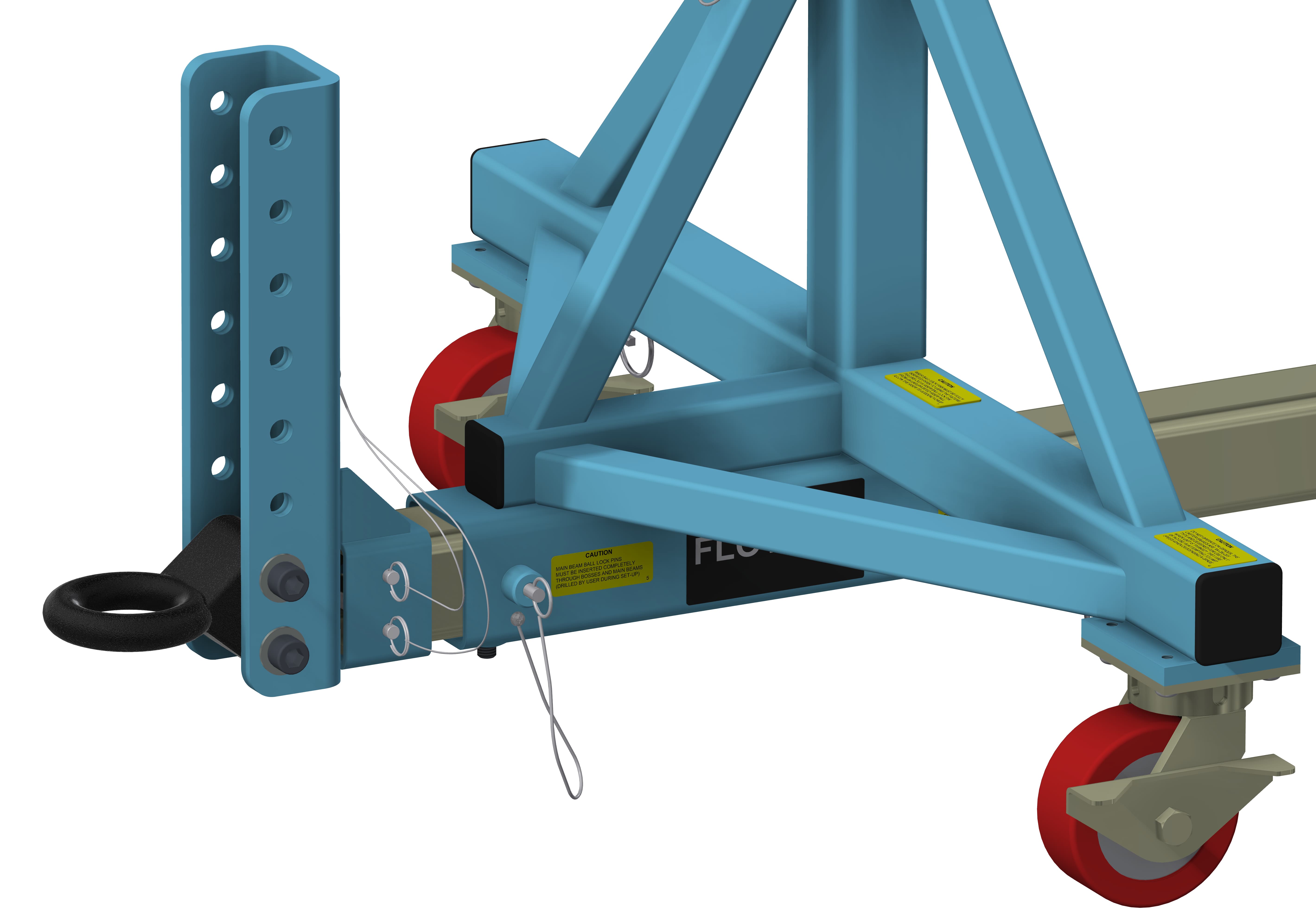
B. Ball Coupler (T2) – The ball coupler accepts a Ø2” ball.

Standard Proof Load Test (PLT):
Proof Load Test Procedure:
Dead weight load (no rotation), visual inspection.
- Static proof load test.
- Vertical load only.
- 200% vertical load, 100% torque.
- Hold load for 5 minutes minimum.
- Customer may witness test.
- Paint and plating covers all welds.
- Visually inspect for cracks, deformation, etc.
A deliverable proof load test report will be provided. The report will include a summary of the test procedure, actual measured weight of load applied, visual inspection results, and images of the test being performed.
Special Options:
If a standard Holding Fixture does not meet your requirements, contact Flotron about custom modifications. Often minor modifications to a standard unit are all you will need and can be done cost efficiently. See here for past examples of our Modified Standards and Custom Solutions.
For 600 Series – Creating a Model Number, click here*